
Contents
RADIOGRAPHY PROCEDURE
SCOPE
This procedure defines and outlines the approach to be employed for performing non-destructive testing on welded joints of steel structures, piping assemblies, on metallic components, and recording the results of the examination. The methods of testing addressed by this procedure include the following: PROCEDURE FOR RADIOGRAPHY
- Radio-graphic testing Stage of inspection: the test shall be conducted prior to and after PWHT if applicable
REFERENCES: PROCEDURE FOR RADIOGRAPHY
ASME SE: Standard Method for Controlling Quality of Radiographic testing.
ASME SE 94: Recommended Practice for Radiographic Testing
AASME SE V: Boiler and Pressure Vessel – Non-Destructive Testing.
ASME B 31.3: Refinery and Process Piping Work.
SNT-TC-1A: Recommended Practice for Personnel Qualification and Certification in Nondestructive Testing.
AWS D 1.1: Reference Document for Radiography testing.
CLICK HERE FOR? NDT SAFETY
RESPONSIBILITIES
QA department shall be responsible for ensuring that all non-destructive testing is carried out accurately, efficiently and expeditiously, in accordance with approved techniques.
It is the responsibility of QA department to ensure that all the results of nondestructive testing are reviewed, interpreted and recorded in accordance with the applicable codes.
PERSONNEL
All personnel carrying out the NDT (non-destructive testing ) shall be suitably trained and qualified to SNT-TC-1A, PCN/CSWIP or recognized national standards.
Only personnel qualified to level I or II shall carry out the interpretation and evaluation of test results.
NDT PROCEDURES- Radio-graphic testing
This procedure defines and outlines the approach to be used for performing the radio-graphic testing on welded joints. It also defines the method of producing radio-graphs, interpretation and evaluation of film images and to ensure that the results of the tests conform to the requirements of the applicable code and project specifications.
Radiation- Is diffusion of ray of light is called radiation . There are two types of radiation:
- Non-ionizing radiation: can cause heating effects in the body, e.g. ultraviolet from arc welding, radiation waves, microwaves; and
- Ionizing radiation: has sufficient energy to penetrate, ionize (change the electrical charge of an atom) and damage body tissue and organs, e.g. x rays, gamma rays, used in non-destructive testing of metal structure.
CLICK HERE FOR? HIRA AND JSA
Non-ionizing Radiography physical hazards
- Burn
- Erythema ( reddening of the skin)
- cataracts
- Arc eye
- Temporary sterility.
Ionizing radiation hazards
Acute effects-
- Erythema: reddening of the skin
- Radiation sickness- nausea, vomiting, diarrhea
- Hair loss
- Death
Chronic effects-
- Mutagenic cancer: various organs, leukemia
- Sterility and hereditary defects
- Teratogenicity effect
- Other effects: eye cataracts, skin damage and death.
Control measures of Non-ionizing radiation and ionizing radiation.
protection measures for ionizing radiation depend upon dose limitation. this can be achieved in three ways:
Time:- The length of time that persons are exposed to ionizing radiation should be kept to a minimum. the main control measures is to ensure that the dose to which persons at risk have been exposed is constantly monitored. Once the cumulative dose limit has been reached they should be removed from exposure.

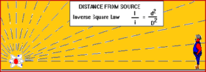
Distance– Segregation by distance reduces the risk to health. Most forms of radiation used in industry will only travels short distances, therefore restricted areas and other controls are required particularly to protect those not involved in the actual operation. In the case of beta radiation for example, the use of tweezers or forceps to handle some sources will greatly reduce the exposure.The energy of ionizing radiation is reduced with distance. It reduces by a quarter for every unit of distance a persons stands away from the source.
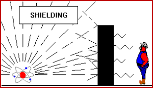
Shielding– Enclosures, ranging from concrete and/ or lead to cardboard depend upon the type of radiation used. A sheet of paper stops alpha particles; a thin sheet of aluminum will stop beta particles. Gamma rays will pass through most materials, but will be stopped by thick lead or concrete; and barriers or screens.
Other factors
- PPE, e.g. Whole body radiation suits
- Environmental and personal monitoring, e.g. film badges
- Correct disposal of radiation materials
- Training and supervision
- Good hygiene practices.
Ensure Radiation safety at site before start the job.
- Bhaba atomic research center (BARC) norms will be implemented in all respect. No deviation Type of equipment and the methods of usage, storage and transportation of radiation emitting equipment shall be complied with radiation safety regulations for ionizing radiation of INDIA.
- Temporary barriers with warning signs bearing international radiation symbol shall mark the radiation areas.The vicinity immediately outside the radiation area shall be manned to ward off potential intruders.
- Radiography agency certificate, radio-graphic badge etc. will be submitted in advance to safety department.
- Calibration certificate of survey meter will be submitted in advance.
- Work permit will be taken one day in advance before commencing radiography.
- All precautions listed in BARC safety guidelines (supplied by company) will be implemented in all respect.
- If radiography is to be done at height than all precautions with respect to working at height will be implemented.
- Storage and transportation of radiation material shall be out-sourced from nearby site location (AP Competent person) as and when required.
- Agency not yet finalized , the agency details will be submit to company once fixed for the radiography work and prior approval shall be obtained.
- Equipment- Generally the Ir192 Gamma ray systems or equivalent shall be used.
- Film- Film Radio-graphic film shall meet the requirements of ASME SE 94. Film shall be checked for fog density, maximum of 0.3 H&D (Transmission Density)
- Intensifying screen-The lead intensifying screens shall be used in accordance with ASTM E94.
Geometrical Un-sharpness.
Geometrical un-sharpness limitations of radio-graphic shall be in accordance with the requirement of ASME Code Section V Article 2 paragraph T -285.
CLICK HERE FOR? PPE IS CODE
Geometrical un-sharpness (Ug) shall be determined as Ug = Fd/D. Where:
F = Effective source size.
D = Distance from source to object being radiographed.
d = Distance from the source side of the object to the film.
Back scattering control
Back scatter will be limited insofar as is practically possible and shall be checked in accordance with BPV Code ASME V Article 2.
Film identification
The radiography shall be clearly identified. The identification of the radiography should be including Project name, drawing number, weld number, welder number (If possible), date of inspection as a minimum.
Weld location from datum point shall be located by lead markers, which shall provide permanent images on radiography. Their location shall be marked on the surface of the examined part to provide tractability.
For repaired welds, the letter “R” shall be placed adjacent next to the weld number for the first repair. “R1” indicates the second repair and “R2” indicates the third repair.
Image quality indicator (IQI)
Type-FE DIN type IQI wires shall be used in accordance with ASME V article 2 table T-276
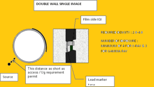
Placement and number of IQI.-IQI shall be placed on the source side where possible. For double wall single image technique the IQI shall be placed on the film side.
CLICK HERE FOR? HSE INTERVIEW QUESTIONS AND ANSWERS
The IQI shall be placed on the weld so that the length of the wires is perpendicular to the length of the weld.
Numbers of IQI : when the length of film to be interpreted is equal or less than 6” (150 mm) one IQI shall be placed diametrically opposite the source at the center of diagnostic area; when the diagnostic film length is greater 6” (150mm) two IQIs shall be used, one shall be within 1 inch (25mm) of the end of diagnostic length and the other shall be diametrically opposite the source.
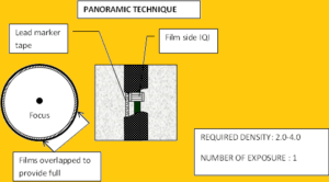
For panoramic technique: four IQIs shall be placed approximately 90 degree apart.
When a repaired weld is re-examined, at least one IQI shall be placed adjacent to each repaired area.
IQI sensitivity
Radio-graphic sensitivity shall be judged by image of IQI. Radio-graphic technique and equipment shall provide sufficient sensitivity to clearly delineate the required wire diameter. The sensitivity shall be a minimum 2%.
Spreparation
The visual inspection of the weld shall be done before radio-graphic testing, to assure that the test piece is free from surface defects and all other irregulars that may interfere with the interpretation of film images.
Radiography density limitations.
A single film, Gamma-ray: 2.0 minimum and 4.0 maximum
Assessment of Quality of Radio-graphs
A radiograph shall be acceptable when:
- It is free from mechanical damage, processing defects such as streaks, watermarks or stains and other blemishes e.g. which may interfere with the interpretation of images.
- Density is in the acceptable range
- IQI sensitivity is acceptable
- Film identification is acceptable
Film processing
The automatic or manual process may be used. Handling, mixing and dilution of chemicals, film processing shall be in accordance with the manufacturer’s recommendation. Final washing: the processed film will be cleaned in running clean water for at least 20 minutes to remove residual chemicals so that radiographic images will get a minimum archival life of 5 years under normal storage conditions. The company may require the test for shelf life.
CLICK HERE FOR? HYDRO TESTING SAFETY
Re-examination.
Any weld showing unacceptable defects shall be repaired then re-examined by the same RT technique as originally used.
Viewing facilities.
Viewing facilities shall be provided with subdued background lighting of intensity that shall not cause troublesome reflections, shadows or glare on the radiograph. Film viewer should provide a light source sufficient for the designated wire to be visible for the specified density range. The viewing conditions shall be such that light from around the outer edge of the radio graph or coming through low-density portions of the radio-graph does not interfere with interpretation.
Acceptance criteria.
For process Piping: Acceptance criteria shall be based on ASME B 31.3 table 341.3.2 A for normal fluid service, with the exception of piping class E.
For structural steel: acceptance criteria shall be in accordance with the requirement of AWS D1.1-98 section 6.12.1 for non-tubular structure and section 6.12.3 for tubular joints.
Records.
All results of radiographic tests of the welded joints shall be reported in the form of a “ Radio-graphic Testing Report “.
The report shall be submitted to the client for approval. The original reports shall be maintained on file and available for review at any time. All radio graphs pertaining to this project shall be stored in a manner that prevents deterioration of the film i.e. a dry clean environment away from direct light.
CLICK HERE FOR? WORK AT HEIGHT SAFETY
Radiographs shall be held in storage and shall be made available to the client for viewing upon request. At the end of the construction/handover phase, films will be handed to the client.
RADIO-GRAPHIC TESTING – EXPOSURE TECHNIQUES
TECHNIQUE NO 1: PROCEDURE FOR RADIOGRAPHY
TECHNIQUE No 2 ( DWSI ):PROCEDURE FOR RADIOGRAPHY
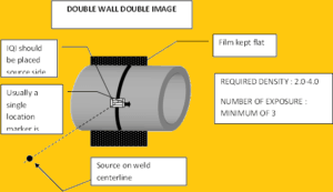
TECHNIQUE No 3 ( DWDI): PROCEDURE FOR RADIOGRAPHY
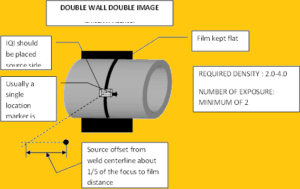
TECHNIQUE No 4 ( DWDI )


sir
i will be happy if yoy arrange to bring out all the published innovative contents and useful topics regarding Health, Safety & Environment, which will help and awareness to people for daily life
in a bookform which may hep for everybody in the field.
with kind regards,
doraisubramani. 05 06 2022.
Very nice and improve my skills and knowledge
Thank You!!
Very nice sir