Fixed Fire Installations
Fixed type fire installations are desirable from the design stage, as they can be used for longer time and are more effective than the portable type:
Fire Hydrants:
Fire hydrants are economical and should be installed freely around the plant. They should be kept accessible, unobstructed and protected for safety. Indicator posts are advisable.
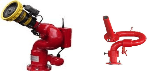
Fire hydrants, hoses, nozzles and couplers are part of the system. Fixed nozzles are single or double headed. Monitor nozzles are on swivel joint and can be turned as desired and to clear any obstruction. Hose nozzles can be extended and laid (more flexible) wherever required. They are of fixed flow type, adjustable flow (variable discharge) type and a combination type.
The number of hydrant needed depends on the fire exposure and the hose-laying distance to the built up areas. The discharge ports should be at least 18 inch (45 cm) above the ground level.
Fire Hose and Nozzles of standard size, double jacketed rubber-lined should be stored in hose boxes and should be subjected to a full pressure lest once a year. Space around hose lines and control valves should be clear. Aisles and doorways should be wide enough and clear to allow rapid use of hose reel cart or mobile equipment.

Monitor Nozzles are used in yards and large congested areas where it is difficult to lay hose line in an emergency. The nozzle is so positioned to direct a high pressure water stream over desired area and height.

Water Reservoirs are necessary for the supply of fire water at good pressure and volume. They should not be used for other purposes such as process requirement. If the reservoir is common, suction pipe (its bottom end) for process water should be at a higher level than the suction pipe for fire water into the bottom of the reservoir to maintain the level of reserved water for fire protection.
Water supply from reliable sources is essential. Reservoirs, overhead tanks, pressure tanks, pumps, pipe and connections must be maintained well. Flow discharge may vary from 10 to 40 litres per second and pressure from 7 to 10 kg./cm2.
TAC guidelines (rules) for water supply for hydrants are as under:
Water for the hydrant service shall be stored in any easily accessible surface or underground lined reservoir or above ground tanks of steel, concrete or masonry. The effective capacity of the reservoir (above) the level of the foot valve seat in case of negative suction and above the level of the top of the pump casing in case of positive suction) for the various classes of occupancies (as per rule 7.2).
Note 1: Reservoirs of and over 2,25,000 litres capacity shall be in two interconnected compartments to facilitate cleaning and repairs.
Note 2: Large natural reservoirs having water capacity exceeding ten times the aggregate water requirements of all the fire pump drawing there from may be left unlined.
Capacity of water storage
| Nature of Risk | Capacity of static storage exclusively reserved or hydrant service |
| 1. Light Hazard | Not less than 1 hour’s aggregate pumping capacity with a minimum of 1,35,000 litres. |
| 2. Ordinary Hazard | Not less than 2 hour’s aggregate pumping capacity. |
| 3. High Hazard (A) | Not less than 3 hour’s aggregate pumping capacity. |
| 4. High Hazard (B) | Not less than 4 hour’s aggregate pumping capacity. |
Note 1: The capacity of the reservoir for Ordinary and High Hazard Class Occupancies may, at the discretion of the Committee, be reduced by 2 hours’ inflow from a reliable source (other than a town’s main) but in no case shall the reservoir capacity be less than 60% of that mentioned above.
Note 2: In case of Light Hazard Class Occupancies the minimum capacity of the reservoir shall be increased to 2,25,000 litres if the highest floor of the building is more than 15 meter above the surrounding ground level.
The capacity for hydrant service shall be determined by the class of occupancy and size of installation.
Pump Capacity and Delivery Pressure:
| Sr. No. | Nature of Risk | Number of hydrants | Pump Capacity in Litres/Sec (M3/Hour) | Delivery pressure at rated capacity kg/cm2 |
| 1. | Light hazard | (A) No exceeding 20 (B) Exceeding 20 but not exceeding 55 (C) Exceeding 55 but not exceeding 100 (D) Exceeding 100 | 27(96) 38(137)
47(171) Plus
47 (171) for every additional 125 hydrants or part thereof.
| 5.6 7
7
7/8.8 |
| Note: The total pumping capacity need not be greater than 190(683) irrespective of the number of hydrant points | ||||
| 2. | Ordinary Hazard | (A) Not exceeding 20 (B) Exceeding 20 but not exceeding 55 (C) Exceeding 55 but not exceeding 100 (D) Exceeding 100
| 38(137) 47(171)
76(273) 76(273) plus 76(273) for every additional 125 hydrant or part thereof | 7 7
7 7/8.8 |
| Note: The total pumping capacity need not be greater than 302(1092) irrespective of the number of hydrant points. | ||||
| 3. | High Hazard (A) | (A) Not exceeding 20 (B) Exceeding 20 but not exceeding 55 (C) Exceeding 55 but not exceeding 100 (D) Exceeding 100 | 47(171) 76(273)
114(410) 114(410) plus 114(410) for every additional 150 hydrants or part thereof. | 7 7/8.3
7/8.8 7/8.8/10.5 |
| 4. | High Hazard (B) | (A) Not exceeding 20 (B) Exceeding 20 but not exceeding 55 (C) Exceeding 55 but not exceeding 100 (D) Exceeding 100 | Two of 47(171) Two of 76(273)
Two of 114(410) Two of 114(410) plus one of 114 (410) for every additional 200 hydrants or part thereof. | 7 7/8.8
7/8.8 7/8.8/10.5 |
This provision will apply only in cases where the hydrant service has been hydraulically designed as per NB 3(b) u/r 7.5.10.
Note: In case of Light Hazard Occupancies the pump delivery pressure will need to be 7kg/cm2 if the highest floor of the risk is at a height exceeding 15 metre above the surrounding ground level.
Proper drainage facility shall be provided to drain the fire-fighting water out of the basement.
Storage of material in the open shall be protected as under:
| Metal, Metallic goods, Machinery and other non-hazardous storage | One single hydrant for every 60 meter Of storage periphery located beyond 2 metre but 15 metre Of storage area |
| Coal or Coke | One single hydrant for every 45 metre of the storage periphery located beyond 2 metre but within 15 metre of storage area. |
| Other Storage | One double hydrant for every 45 metre of the storage periphery located beyond 2 metre but within 22.5 metre of storage area. |
Note 1: In case of open storage areas of following materials, at least 50% of hydrants shall be replaced by fixed monitors having nozzle bore of 38mm diameter if the individual stack height is more than 6 metre and total storage exceeds 5000 tonnes.
Note 2: Where hydrant/monitors located along one longer side of a storage area are more than 90 metre from those along the other longer side, such a storage area shall not be deemed to protected.
Protection for combustible/flammable liquid Storage Tanks:
| Tank less than 20 metre in diameter | One double headed preferably two single headed hydrants located beyond 15 metre but within 35 metre of tank shell. |
| Tanks over 20 metre in diameter | Two double headed or four single headed hydrants located beyond 15 metre but within 35 metre of tank shell. |
Note 1: In case tanks are located more than 22.5 metre from the dyke walls, one double hydrant or two single hydrants shall be replaced by a 38 mm monitor.
Note 2: Where the distance of tank from the monitor exceeds 45 metre in addition to provisions of Note 1, the tank shall be protected by Fixed Foam or Medium Velocity Water Spray System having prior approval of the Committee.
Note 3: Hydrants/Monitors shall not be installed within dyked enclosures nor can the hydrant main pass through it.
Note 4: Fixed roof type storage tanks, floating roof type storage tanks exceeding 30 metre in diameter and Bullets/Spheres containing products having flashpoint below 32 degree centigrade shall be protected by Medium Velocity Water Spray System conforming to relevant regulations.
However, manually-operated systems shall also be acceptable. Water spray systems shall not be insisted for Insulated vessels/Spheres.
Water spray protection for small size tanks up to 10 metre diameters in ordinary and high hazard risks shall not be insisted upon.
Automatic Water Sprinklers:
They are of six types.
- Wet pipe
- Dry pipe
- Pre-action
- Deluge
- Combined dry pipe and pre-action
- Sprinklers for limited water supply system
Automatic alarm operated by the flow of water should be a part of sprinkler installation. Such an alarm may be connected to a central fire station. The sprinklers should be regularly checked to avoid their failure to work.
Automatic sprinklers are most efficient and widely used. It reduces insurance premium considerably.
Its basic function is to spray water automatically to fire, the system can also work as a fire alarm. This can be done by installing an electrical water flow alarm switch in each main riser pipe.
Sprinklers should be selected on the basis of temperature rating and occupancy. Their type are-Either heat-element or chemical melts or expands to open the sprinkler. Normal detector setting is 68 degree centigrade. Sprinklers heads normally cover 12m3 per head. Amount of water required depends on risk protected flow range being 0.04 to 0.514 I/m2.
In deluge system, water is admitted to sprinklers that are open at all times. Deluge valves (water supply valves) can be operated manually or automatically by an automatic detection system.
Maintenance and inspection of water supply valves, system piping for obstruction, nozzles and water supply tests etc. are necessary.
Water Spray System:
Water spray system uses water in small droplets through special nozzles giving various pressures. The system is supplemented to and not a replacement for automatic sprinklers. It should be checked that the water should not be reactive with the material burning.
The system is similar to the deluge system except that the open sprinklers are replaced by spray nozzles. The system is generally applied to flammable liquid and gas tanks, piping and equipment, electrical equipment such as oil filled transformers, switches and motors. To avoid short circuit, current should be cut off before applying the spray.
The spray nozzle holes are smaller than those in ordinary sprinklers, therefore they can be choked. To avoid this, strainers (filter or screen) are required in water supply lines. The nozzles having the smallest holes, have their own internal strainer in addition to the supply line strainer.
TAC guidelines on Water Spray Systems give detailed rules. Some extract is given below:
Definitions and terminology relating to the components of the water spray systems are as follows:
Water Spray System: A special fixed pipe system connected to a reliable source of fire protection water supply and equipped with water spray nozzles for specific water discharge and distribution over the surface or area to be protected. The piping system is connected to the water supply through an automatically actuated Deluge Valve which initiates flow of water. Automatic actuation is achieved by operation of automatic detecting equipment installed along with water spray nozzles. There are two types of systems namely High Velocity and Medium Velocity systems. The former is useful for liquids with flash point above 65 degree centigrade and the latter for flash point below 65 degree centigrade.
Spray Nozzle and Valves: A normally open water discharge device which, when supplied with water under pressure will distribute the water in a special directional pattern peculiar to the particular device. Nozzles used for High Velocity Water Spray system are called “Projectors” and nozzles used for Medium Velocity Water Spray system are called “Sprayers”. Both these nozzles are made in arrange of orifice sizes with varying discharge angles so that discharge can be controlled for optimum protection.
Different types of valves are used with fire water piping system or water hydrants.
Deluge Valve: A quick opening valve which admits water automatically to a system of projectors or sprayers and is operated by a system of detectors and/or sprinklers installed in the same areas as nozzles.
Control of Burning: Application of water spray to structures or equipment to limit absorption of heat to a level which will minimise damage and prevent failure whether source of heat is external or internal.
Impingement: The striking of a protected surface by water droplets issuing directly from projectors and/or sprayers.
Run Down: The downward travel of water along a surface caused by the momentum of the water or by gravity.
Slippage: The horizontal component of the travel of water along the surface beyond the point of contact caused by the momentum of water.
Insulated Equipment: Equipment, structures, vessels provided with insulation which for the expected duration of exposure, will protect steel from exceeding a temperature of 454 degree centigrade for structural member and 343 degree centigrade for vessels.
Density: The unit rate of water application to an area or surface expressed in litres/min/m2.
Automatic Detection Equipment: Equipment which will automatically detect one or more components directly related to combustion such as heat, smoke, flame and other phenomenon and automatic actuation of alarm and protection equipment.
Fire Barrier: It is a continuous wall or floor that is designed and constructed to limit the spread of fire.
Range Pipes: Pipes on which sprinklers are attached either directly or through short arm pipes which do not exceed 30 cm in length.
Distribution Pipe: Pipes which directly feed the range pipes.
Testing and maintenance of water spray system is given below:-
| Sr. | Subject | Activities | Duration | ||||||||||||
| 1 | Reservoir |
| |||||||||||||
| 2 | Pump |
| |||||||||||||
| 3 | Engine |
| |||||||||||||
| 4 | Motor |
| |||||||||||||
| 5 | Main piping |
| |||||||||||||
| 6 | Sluice valve |
| |||||||||||||
| 7
| Deluge valves |
| |||||||||||||
| 8 | Sprayers |
| |||||||||||||
| 9 | Detectors |
| |||||||||||||
| 10 | Spray installation |
| |||||||||||||
| 11 | Pressure gauge |
| |||||||||||||
| 12 | Painting of entire installation | Every 2 years | |||||||||||||
Foam System:
It uses fixed foam apparatus either automatic or manual. It may consist of one or more portable foam extinguishers suspended in such a way that flame or heat releases a cord or fusible link to operate the extinguisher automatically. Discharge rate may vary from 15 to 4000 gpm. Foams are of two types – Chemical and Mechanical. Chemical foam is produced by a chemical reaction of CO2 bubbles and a foaming agent. Mechanical foam is created when air and water are mechanically agitated with a foam solution.
Fire fighting foam (gas-filled bubble solution) is lighter than most flammable liquids. Therefore it forms a floating blanket on burning liquid, cuts off oxygen supply and also cools the fuel.
Foam system is generally used to protect fuel tanks, oil and paint storage rooms, asphalt coating etc. It can be injected on the liquid surface in a tank to provide blanketing effect and to cut off flames and vapours.
Foam is of two types – Low expansion and High expansion foam. Low expansion foam is of four types Chemical foam, Mechanical or air-generated foam, Protein foam and Synthetic (fluorinated surface active agent) foam. Foam generators of different types are available.
Foam water sprinkler and spray systems use mechanical foam equipment with a deluge sprinkler system.
High-expansion foam is best suited for class A and B fires in confined spaces such as sewers, basement. It is made by mixing a small amount (@1.5%) of foam liquid into a foam generator where water and large quantities of air are mixed. Accumulated foam can act as an insulating barrier for the surface not involved in fire. Thus it prevents fire spread.
Ventilation is necessary to vent the displaced air and gases when foam is being applied.
Carbon dioxide system:
These are fixed local or flood type. They are generally useful for electrical, liquid and gas fires.
CO2 system may be of high-pressure or low-pressure type. In the high pressure system CO2 is kept in a compressed gas cylinder at normal temperature while in the low pressure system it is stored in an insulated pressure vessel at – 18 degree centigrade and 300 psi by mechanical refrigeration. At such low temperature more CO2 can be stored economically. Safety valves are provided to take care of refrigeration failure. Liquid CO2 can be delivered through nozzles at 15 kg/sec.
In both the systems, CO2 can be released manually or automatically through nozzles close to the expected source of fire. Unlike water or chemical, CO2 does not spoil the stock or equipment.
In a room, compartment or small building, total flood system can be used where wall openings can automatically be shut when the gas is released. Warning alarm to alert people working nearby is necessary. Sufficient time must be allowed to evacuate the area.
In a confined place, the area should be well ventilated and checked for O2 content after the fire is extinguished.
Dry Chemical Powder (DCP)
Dry Chemical Powder is neither toxic nor conductor of electricity, nor does it freeze. It is stored in an inert gas cylinder under pressure. Installations can be provided for simultaneous closing of fire doors, windows, ventilating ducts, operating valves, shutting off fans and machinery and actuating alarms.
The dry chemical piped systems are developed for fast extinguishment in a confined area or for localised application. They are useful on flammable liquid and electrical hazards and can be operated manually, automatically or remotely. The agent is kept in a pressurised container fixed or mounted on vehicles.
Action of extinguishment is to interrupt the chain reaction of fire by the dry chemical agent.
Dry chemicals include Sodium bicarbonate as standard dry chemical, Potassium bicarbonate, General purpose powder (ABC) and Monnex powder. If electrical equipment is not involved, foam can be used to follow DCP application.
Vaporising Liquid System:
It uses carbon tetrachloride, methyl bromide as an extinguishing agent(banned in some country). All these being toxic, care in handling (with PPE) is essential.
Steam System:
It uses automatic or manually controlled steam jets to smoother fire in closed containers or small rooms. It is practicable where continuous steam is available. It is not effective on deep-steam fires Precautions against burns should be followed.
Inert Gas System:
It uses CO2, N2, flue gas or other inert gas to replace O2 in air. Oxygen should be reduced between 5 to 16% depending upon the combustible material involved. After the use, the place should be thoroughly ventilated and tested for normal oxygen for re-entry.
Air Agitation:
It uses air or other gas injection to induce in the tank or container an upward flow from the colder (bottom) surface to the burning (upper) surface, thereby cooling the surface. Generally this system is useful for small oil fires in tank or container.
Drenchers:
Drenchers in roof, wall or window throw water outside the building to protect it from fires coming from outside. A drencher system is made up of water heads similar to sprinklers.


