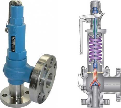
Over pressure Protection and Pressure Relief Devices: Pressure exceeding the maximum permissible working pressure (MPWP) of a pressure vessel poses high hazard and needs pressure relief devices.
Rule 61 of the Gujarat Factories Rules requires safety valve or pressure relieving device, suitable pressure gauge, stop or isolation valve to shut off pressure source, drain valve, pressure reducing valve or automatic pressure regulator.
CLICK HERE FOR ? PRESSURE TESTING (Hydro & Pneumatic) SAFETY PROCEDURE
IS:2825, Section 1, Part 5 gives much details or this subject. It requires as under-
- Fully liquid filled vessels should have liquid relief valve.
- If a vessel is filled with a heating coil or element pressure increase due to its overheating, should be considered while designing relieving capacity of the protective device.
- Vessels operating under pressure and vacuum (due to cooling of content) both, should have a combined pressure vacuum relief device.
- Vessels operating under vacuum should have a vacuum break relief device.
- Pilot or other indirect control valve alone are not permitted. Main valve opening at a set pressure automatically must be provided. The relief valve shall be so designed that they cannot be inadvertently loaded beyond the set pressure.
- Bursting (Rupture) Discs are preferred where pressure rise is fast like explosion, or where choking may make the safety valve inoperative and where even minute leakage of fluids cannot be tolerated (because of high toxicity or flammability). The disc may be mounted independently or in series with a relief valve provided that the bursting pressure of the disc shall not exceed MPWP of the vessel and its opening (diameter) should be sufficient to prevent interference with the proper functioning of the relief valve. If the disc is fitted on the discharge (outlet) side of the valve, back pressure should not be built-up to reduce the lifting pressure of the valve. The disc shall be marked with bursting pressure at a specified temperature and shall burst within +/- 5% of that bursting pressure.
- The relief valve shall be of sufficient capacity to discharge the maximum quantity of the fluid and when it is discharge pressure in the vessel should not rise of more than 10% above the set pressure.
- Set pressure of the pressure relieving device (valve or disc) shall not exceed MPWP. This setting pressure will include the effect of static head and constant back pressure. If more than one protective device is provided, only one be set at MPWP and other devices at pressure not more than 5% in excess of the MPWP.
- Vapour relief valve shall be provided in vapour space and liquid relief valve in below the liquid level.
- Discharge line (after relief device) diameter shall not be less than that of the relief device outlet. Size of drainage or blow-down tank should be such that it will not reduce the relieving capacity of the relief device. Discharge lines shall be properly anchored, particularly at their open ends, not to allow any displacement.
Let us see some practical examples which can cause accidents. Where a pump feeds a receiver, the safety valve should pass the volume being pumped if it has to open. In distillation column where normally there is no pressure, overpressure may be created due to increased heat input because of cooling failure or loss of reflux or loss of sub cooled feed and increase in temperature difference in re-boiler. Therefore safety valve becomes necessary on distillation vessel or column. Low pressure storage tanks can withstand a very low pressure. Safety valve should be provided on it to tackle any accidental pressure rise. Safety valve of low pressure side of a heat exchanger should be sized to handle the flow from twice the cross sectional area of the high pressure tube in the exchanger to relieve its sudden bursting pressure.
CLICK HERE FOR ? STATIC AND MOBILE (UNFIRED) PRESSURE VESSELS RULES 1981
To check whether safety valves operate reliably they should be daily opened by hand.
The number of safety valve on any vessel depends on the volume of working fluid and discharge capacity of the valves.
High noise is created by blow-down of safety valves. Engineering control to reduce this noise are necessary. Workers in safety valves testing area should wear ear, eye and hand protections.
Water seal is used on pressure vessels that operate at low pressure or slight vacuum such as alcohol stills and gas holders. A U-pipe filled with water with one end connected to the pressure side and other end open workers as a low pressure safety valve.
Depressurising devices or pressure interlocks are required on autoclaves, vulcanises, digesters, jet dyeing vessels, retorts etc. where charging doors are to be opened. The device or interlock will prevent the door opening till all pressure inside is relieved or prevent the pressure build-up till the door is closed.
CLICK HERE FOR ? Pressure Vessels and their Safety Aspect
High pressure alarms give audio visual alarm that the pressure is being increased. They are useful when pressure relief device may not work. In that event a vent valve or discharge valve should be manually or remotely opened and the reason of non-functioning of the relief device at its set pressure should be investigated.
Pressure/Temperature recorders or printouts are useful to study the process behaviour or investigate an accident happened on the system.
FLARE:

In plants where highly toxic or flammable gases are generated in bulk or continuously, a flare system becomes necessary for their collection and safe discharge by burning at height. The flare should be designed to vent the gases during normal operations and emergency conditions. Maximum possible discharge at a time should be considered for safer venting and preventing pollution of the environment.
CLICK HERE FOR ? Safety Aspects of Instruments
A flare system consists of a flare stack and piping to collect the gases to be vented. At the flare tip, steam nozzles are provided for air entrainment and seals to prevent flashback of the flame. At the base a knockout drum is provided to collect the liquid from the gases passing to the flare.
Wet gases and dry, cold gases are collected through separate lines. A low level and a high level flare can be combined together so that normal operating and start-up loads are handled by the low level flare, while both flare are used to handle occasional high volume emergency loads. Thus an environmental impact of flaring can be kept to a minimum.
An intense heat radiation occurs from a flare. Therefore it should have sufficient height and no population in surrounding area.
CLICK HERE FOR ? INSTRUMENT SYSTEM FOR SAFETY
Hazards associated with flaring are-
- Obstruction in the flare system.
- Explosion in the flare system.
- Low temperature embrittlement of pipe work.
- Emission of toxic materials from the flare.
- Heat radiation from the flare.
- Liquid carryover from the flare.
The last three are environmentally objectionable. Smoke, glare and noise of the flare may also cause problems.
Efficient combustion in the flame is necessary otherwise a smoky flame will result. Liquid carryover can also result in smoky flame. By good mixing of fuel gas, steam supply and air entrainment good combustion is achieved. For this, the operator relies on visual observation. An automatic system operates based on flame root temperature.
CLICK HERE FOR ? INSTRUMENTATION FOR SAFE PLANT OPERATION
Because of the air entering down in the stack when the flame may not be working or when any valves are open or due to corrosion this air and flammable gas may enter in explosive range and may explode. To avoid such air explosion, measures taken are purge gas, leak elimination, monitoring oxygen concentration, water seals, molecular seals and flame arresters.
A fuel gas is used as a purge gas to maintain positive pressure in the system to disallow air inside this can be confirmed (no air intake) by monitoring oxygen content.


